Roger P
Well-known member
FINISHED HIGH TECH UDS UGLY DRUM SMOKER
Here are details of my high tech DIY UDS. It might give you ideas on how to build your own so feel free to copy anything that might work for you. Construction details follow in the posts below. These are not step-by-step, just a review of what I remember over the six months or so during construction.. This is a work in progress so there are a few modifications that will be made as time goes by and I'll update accordingly.
Background
Just for fun, I've bought, then sold, a number of used smokers off Craigslist over the years, both electric and charcoal, to find out what works best for me. My latest is a Masterbuilt 30" electric. It works OK but it has some drawbacks. After a while, I started thinking about a DIY drum smoker.
Although I prefer the taste and texture resulting from charcoal smoking, I'm getting lazy in my old age and wanted instant start up, minimum hassle, and minimum cleanup. Low operating cost was also a factor. And one big constraint was size: not much free space in the covered patio area. All these factors led to an electric smoker/roaster with a compact, vertical design.
Here is a partial list of the features I wanted:
1) A rotisserie for self-basting. I noticed that a spice rub is much tastier when it is frequently basted but I'm too lazy to do it by hand. 2) Precision temp control. I like the idea of tightly controlling the smoker temp as the final meat temp is approaching. 3) Low operating cost. With a typical electric a four hour smoke turns out to cost less than a buck in electricity. Much less if the smoker is well insulated - the goal was 10 cents per hour. 4) Easy cleanup. Although internal soot build up is not an issue for me, I don't like the accumulation of food splatters in my smoker. 5) Big cooking surface area. I often do a big batch with extra for the freezer. And 6) Lots of flexibility: with water pan, without; with lava rock, without; with hot smoke or cold smoke; high temps for roasting and browning, and low temps food dehydrating like jerky.
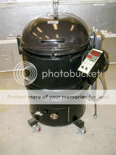
In short, I wanted it all. So I finally settled on a DIY drum smoker. Here is the result:
Wide Mouth

Overview
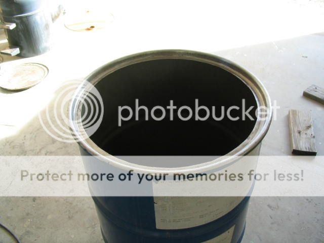
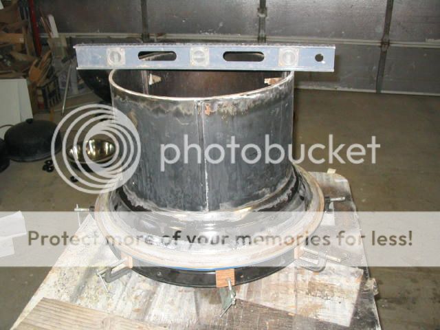
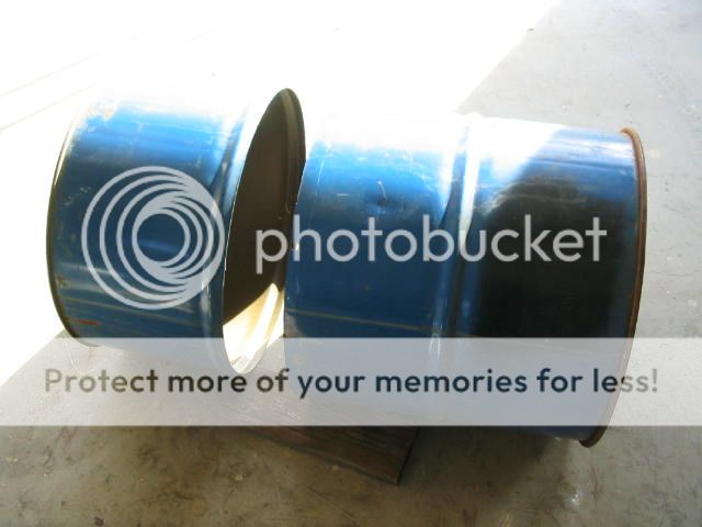
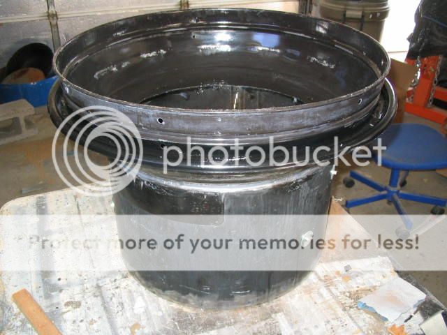
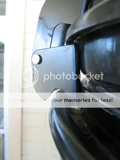
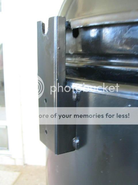
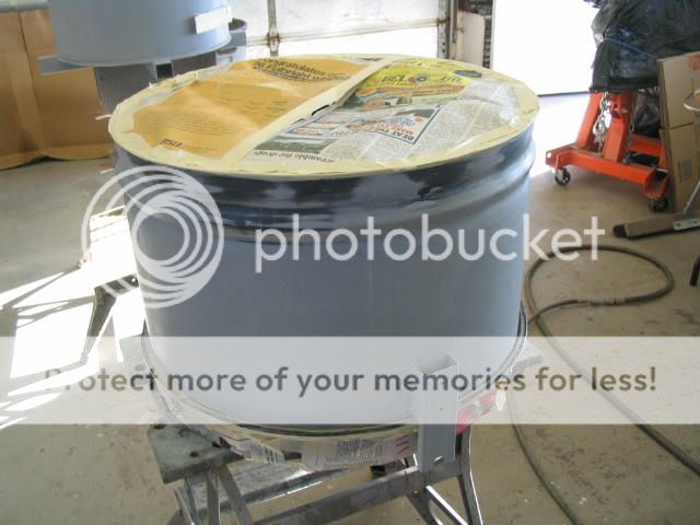
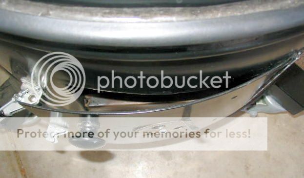
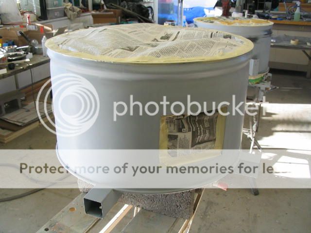
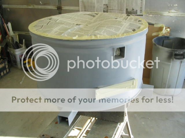
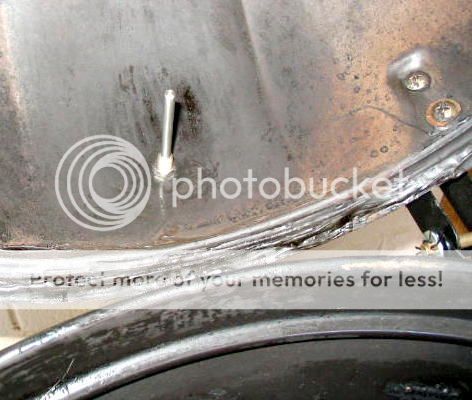
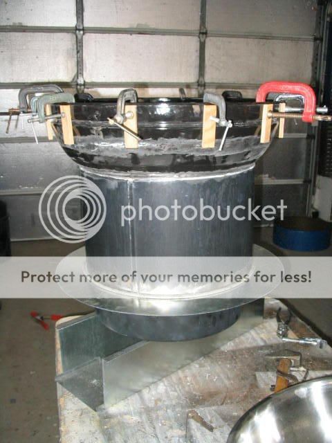
If you look closely at the top photo, the 55 gal drum has been split in two, separated by a rubber gasket. This forms two insulated housings for the internal parts. Below is a photo of the smoker in two pieces. They are held together by locating pins to keep the two aligned. Latches are planned later. If you are into electric smokers the photo below might remind you of an electric Brinkmann unit -- you guessed it.
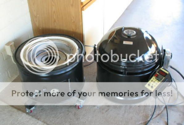
Actually the drum itself is not a key part of the smoker. It simply forms the outside shell for the parts inside. At the seam between the two, the top and bottom are sealed off with a welded round sheet metal ring, then with gaskets.
Layout
There are three main assemblies inside:
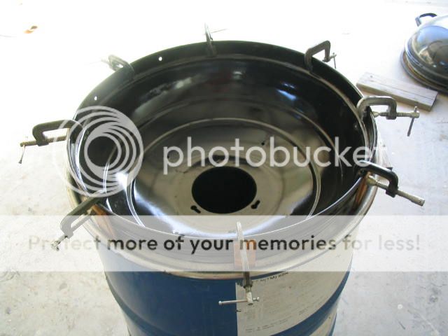
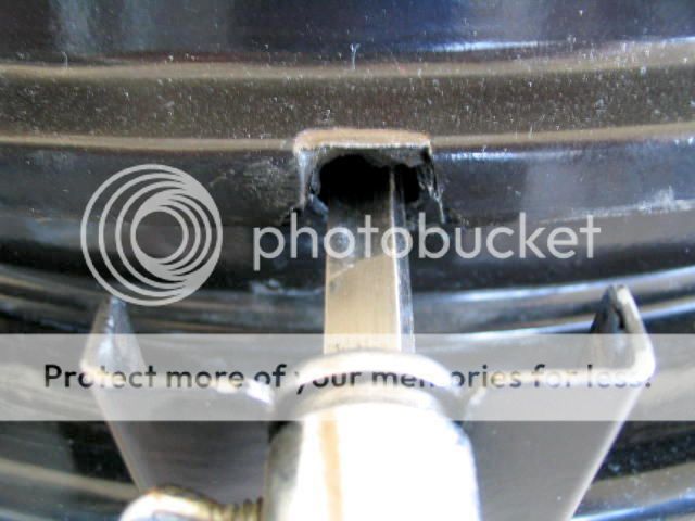
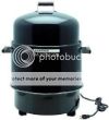
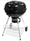
First the top half consists of a UniFlame 360 sq in Kettle Charcoal Grill from Walmart which forms the hinged top, top grill support, and rotisserie shaft cutout. Second, the inside parts are from a Brinkmann (810-5290-4 Smoke'N Grill) electric smoker, less the top, handles, and feet. They look like this:
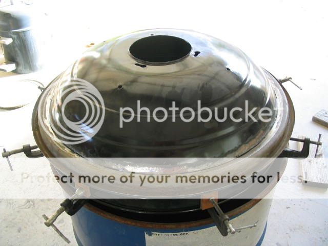
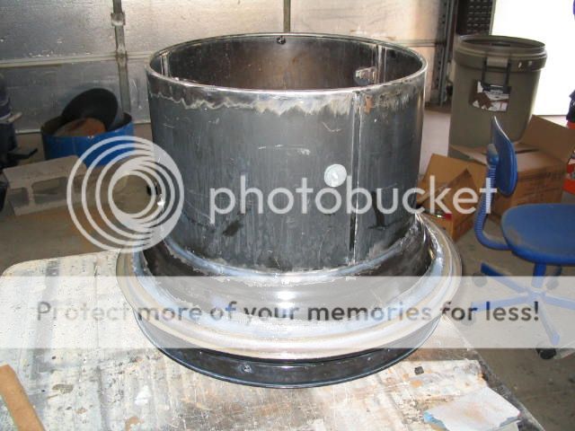
 The Brinkmann body tube was welded to the bottom half of the UniFlame BBQ. The other end of the Brinkmann tube was welded to a sheet metal sealing ring withe drum on the outside between the two. You can see the top half is simply an insulated tube with the BBQ top welded to the top of the tube, and surrounded by the drum.
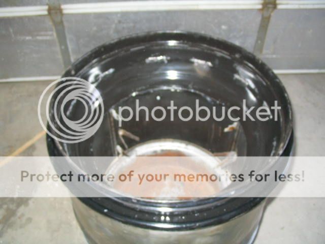
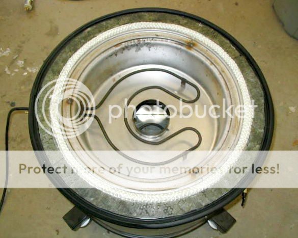
This top assembly then fit into the Brinkmann lava rock pan containing the heating element and below that the base pan. Then, below that is a custom fabricated auxiliary heating element assembly.
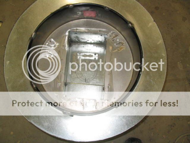
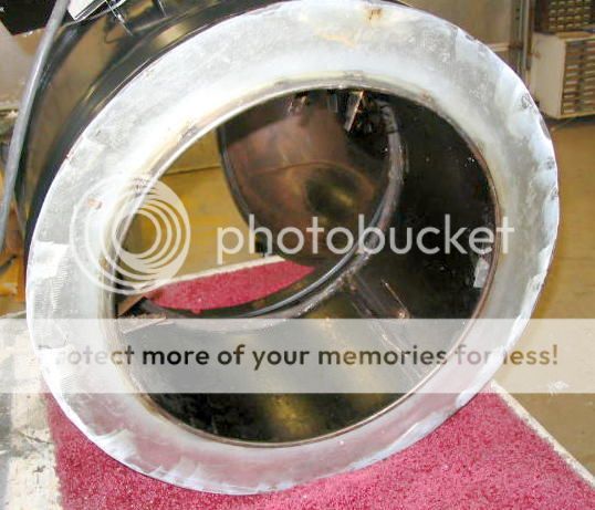
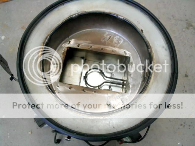
Inside it looks like this:
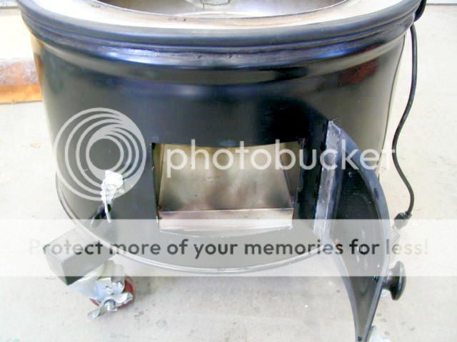
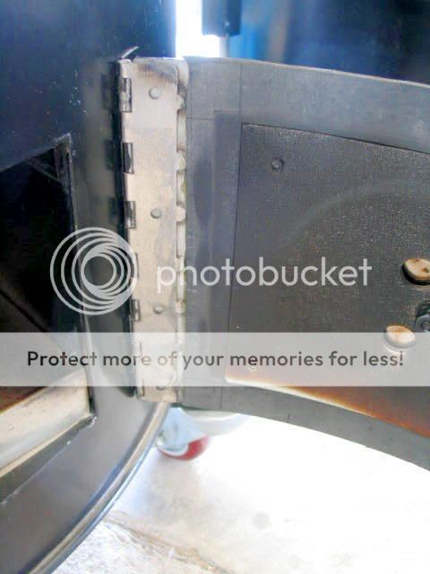
The third part is the bottom sheet metal assembly which contains a Little Chief 250W auxiliary heating element. This second heating element adds heat to the main heating element to achieve higher temps, up to 350 deg. Also, the second heating element allows an independent and controllable source for burning the wood chips. The drum encloses all these pieces with an insulated space between. When both halves of the drum are together, access to the second burner is through through a door in the side of the drum. By splitting in two there is full access for cleaning plus easy access to the heating elements in case they need replacement.
The UniFlame, the Brinkmann, and the drum were all bought used from Craigslist for $15 each. The custom smoke chamber parts were made for about $50 from a local AC sheet metal shop, and the Little Chief heating element was $20 from eBay. So with less than $100 initially invested I was able to get started.
Highlights
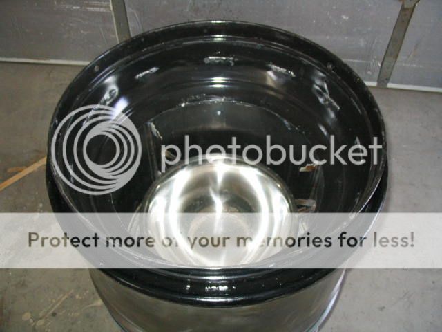
Insulation And Seals
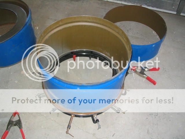
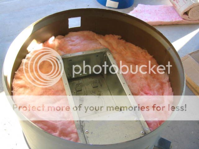
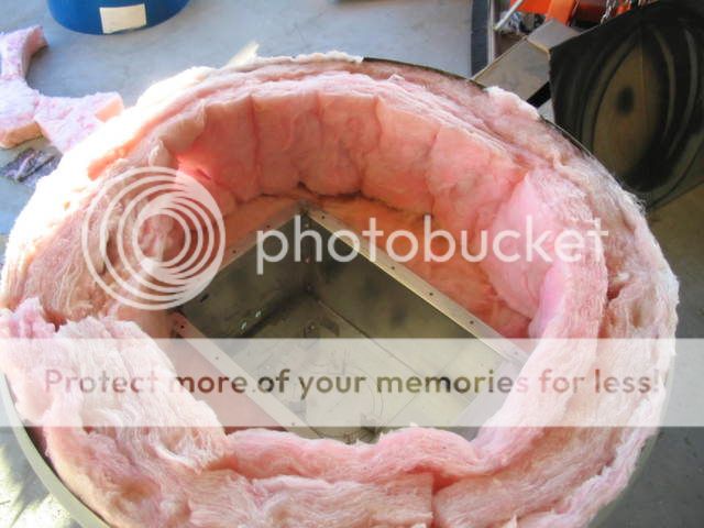
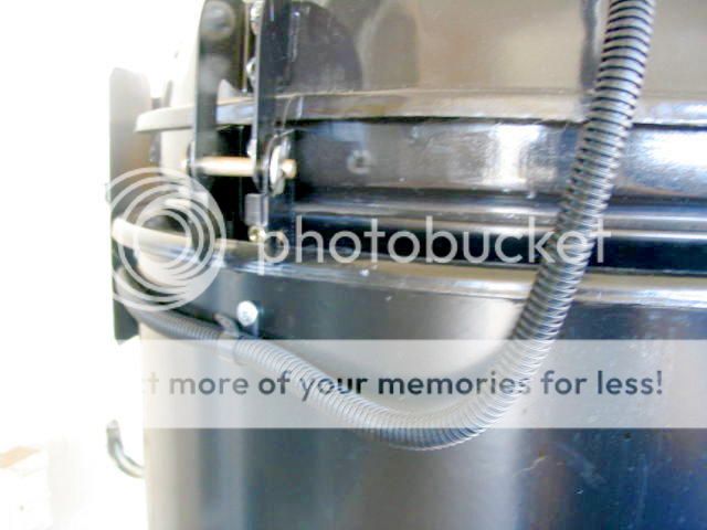
The drum is not really required for this smoker to work. However, it formed an outside housing with about a 3" space between the internal parts. This was filled with fiberglass insulation and fully sealed with silicone sealant.
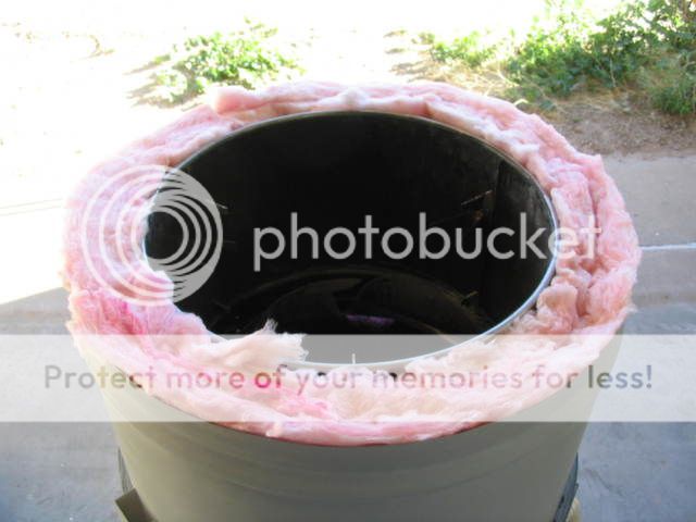
Since the drum surface temperature does not exceed 150 deg at any one spot, most of the the outside surface is just warm to the touch so the drum's inside wall coating did not need to be burned out. With less heat loss it uses less electricity, higher temps can be achieved, and it makes for easier temperature control. A couple small holes in the top and the bottom provides humidity and pressure equalization.
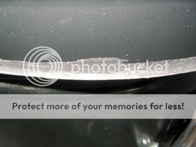
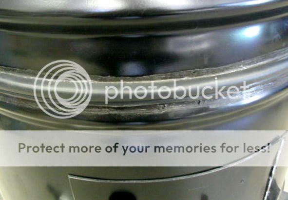
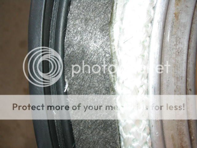
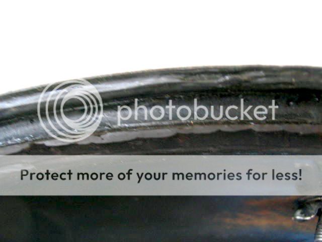
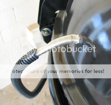
All the seams have been sealed with 500 deg F high temp silicone to prevent air leakage and to prevent the fiberglass insulation from infiltrating into the cooking space. And the area where the two halves of the drums meet was doubled sealed, first with white fiberglass insulation rope on the inside, then a black rubber gasket on the outside, with the gray fiberglass insulation in between.
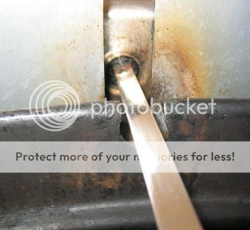
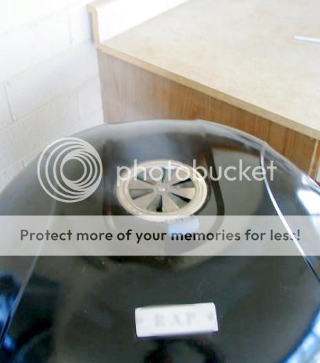
High temperature silicone sealant was used to provide a gasket between the top and the rim. In operation, the only leaks are at the rotisserie rod holes. Of course the top vent operates normally.
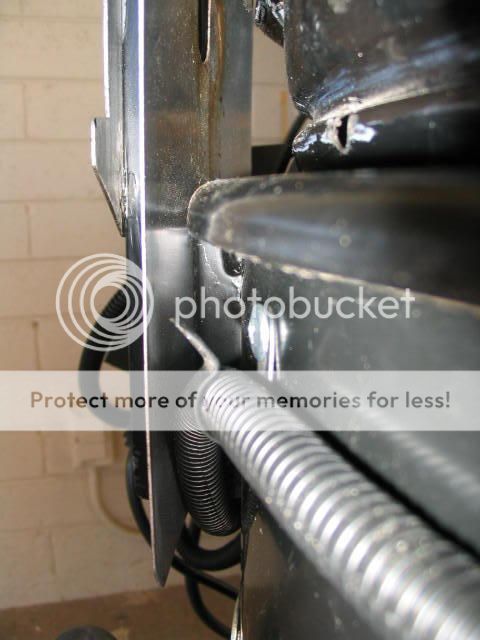
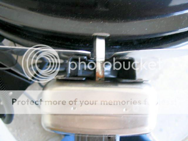
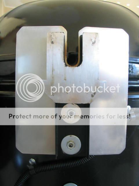
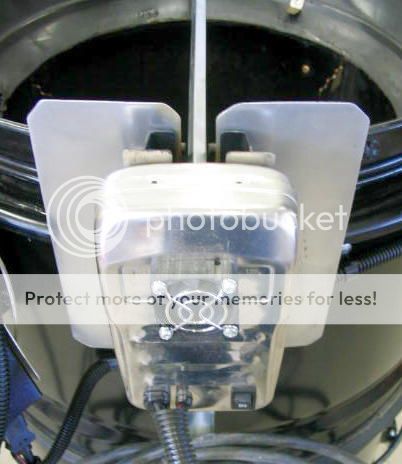
Rotisserie
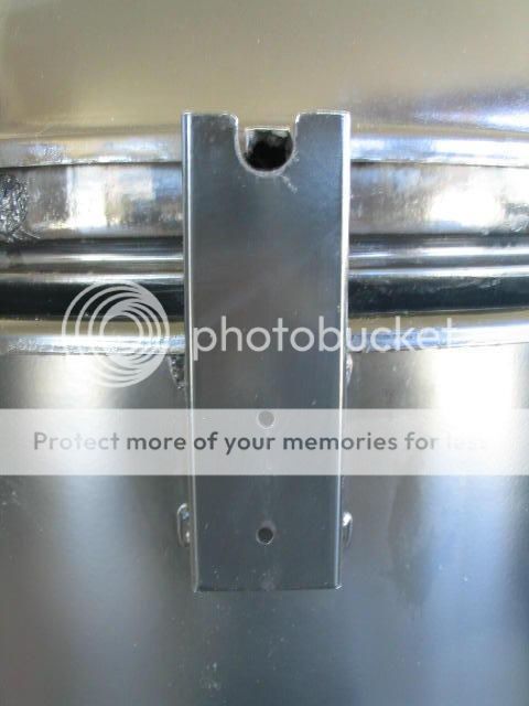
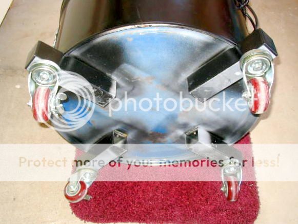
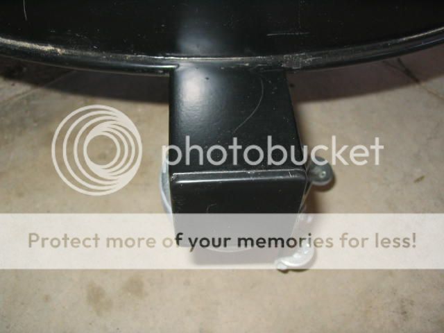
The rotisserie was mounted close to the drum body on a bracket to reduce the overall width. But during testing the rotisserie motor got a little hot. Some motors don't seem to last very long, probably due to the heat. To reduce motor temps a polished heat shield was added, plus a small fan was mounted to the back of the motor near the gearbox. With the smoker's internal temps going full blast the motor now runs only warm to the touch.
Cooking Area
The original top UniFlame grill fits as usual. Below that three tabs were installed so a second grill to fit just below.
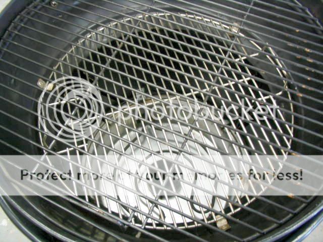
Below the BBQ grill, two Brinkmann smoker grills fit as usual. This allows for a large cook area.
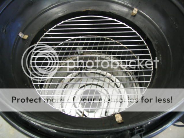
Double Drip Pans
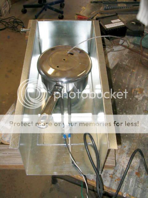
The original Brinkmann water-drip pan still fits but additional pan supports were added for a deeper stainless pan for longer periods between adding water.
Another drip pan can be added to cover a larger area closer to the top and direct the drips to the water pan below.
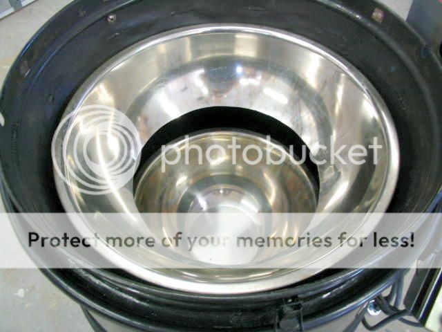
This prevents drips from accumulating at the bottom of the smoker. The pans simply lift out for easy cleaning.
Dual Heating Elements
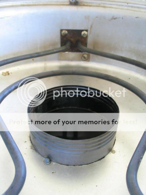
There are two heating elements, the usual Brinkmann element (see previous photo) plus a Little Chief second auxiliary for extra heat and for the wood chips. The aux heating element assembly is mated to the bottom of the Brinkmann base pan.
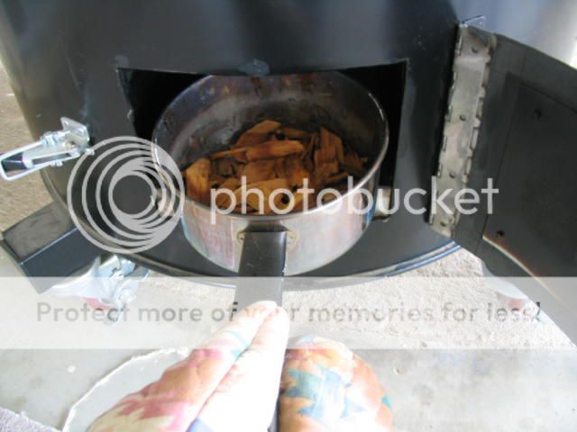
Here is the rationale: First I wanted as much heat as possible to get the internal temps into the 350 deg range so the extra 250 watts adds to the Brinkmann's 1500 watts. Second, I wanted independent control of heating the wood chips so a pan containing the chips fits directly on top of the axillary heating element.
Ordinarily if the smoker is well insulated and the temperature control is tight, the heating element might not cycle hot enough to keep the chips smoldering. On the other hand, if the heating element is cycled hot enough to get the chips going, then the inside temp might swing too high -- not an easy compromise. And with most electrics, getting the smoke chips smoking and replenished over the course of cooking is sometimes a hassle. With a separate chamber for the wood chips accessible from a door on the side, managing the smoke is a snap. There are internal stops to precisely position the chip pan directly on the center of the heating element.
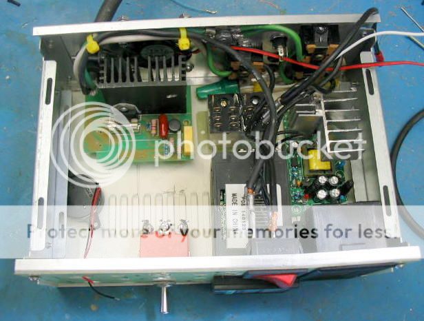
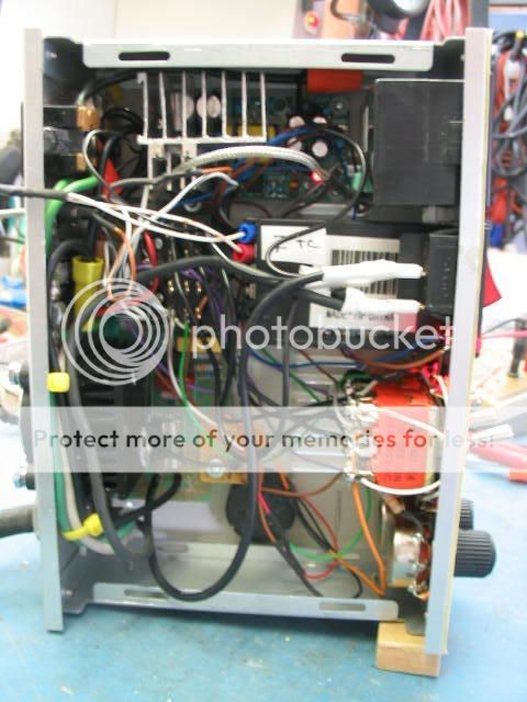
Control Box
The over-the-top control box was designed to provide as much flexibility in controlling temperature and smoke as possible - initially just for fun and dinking around. Thereafter, much of the features included will likely not be used much.
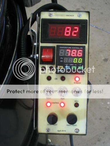
The top display is a calibrated meat thermometer. This is extremely important to minimize opening the top to check the meat temp. When not in use the probe is stored away in the control box mounting.
The square display next to the power button is a dual mode industrial PID temperature controller. (See: wikipedia.org/wiki/PID_controller ) This reads the thermocouple inside the unit and cycles the heating elements on and off to keep the desired temperature.
The two LEDs under the power switch indicate the on-off status of the main and aux heating element.
There are three toggle switches; from left to right: The main heating element can be manually be set to "on" or "off" or connected to the controller in "control." Same for the center switch for the aux heating element. The third switch links the aux heating element to the controller normally, or in reverse.
The two knobs control the power delivered to the heating elements through a solid state AC controller in both the "on" and "off" state. The left knob will add heat when the controller turns the heater off, from zero in the leftmost position and about 700 watts in the rightmost position. The knob on the right controls the wattage when the heating elements are on, from about 700 watts in the leftmost position to about 1750 watts in the rightmost position. Different settings are used depending on the configuration of the temp controller.
Results
With the very first automatic PID setting, the temperature controller easily held plus-minus one degree, about as good at it gets. After the top is lifted the unit gets back up to temp quickly - better than expected, even without the lava rock. But it takes quite a while for the smoker to get from 250 deg to 350 deg so extra time had to be figured in. It takes about an hour for the water pan to get to a gentle boil. With an outside temp of about 100 deg, the unit pulled an average of about 600 watts when set at 250 deg. So a four hour smoke runs less than $0.40 in electricity at our $0.15 KWH rate.
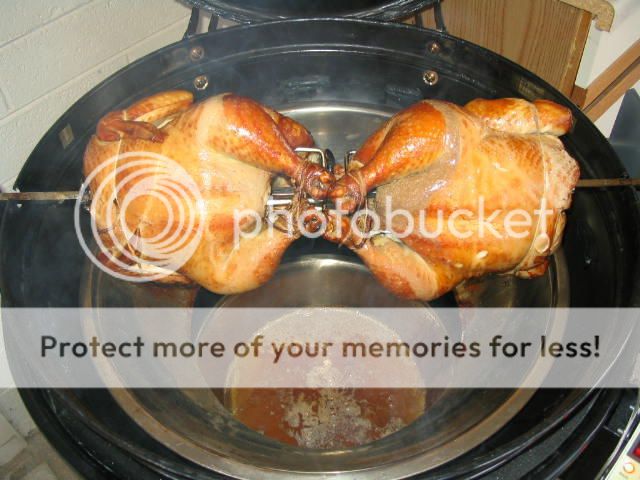
Here are a couple chickens. For testing these were placed with the legs in the middle so most of the drips would fall toward the outside. Only two handfuls of cherry wood chips were used for taste on the mild side.
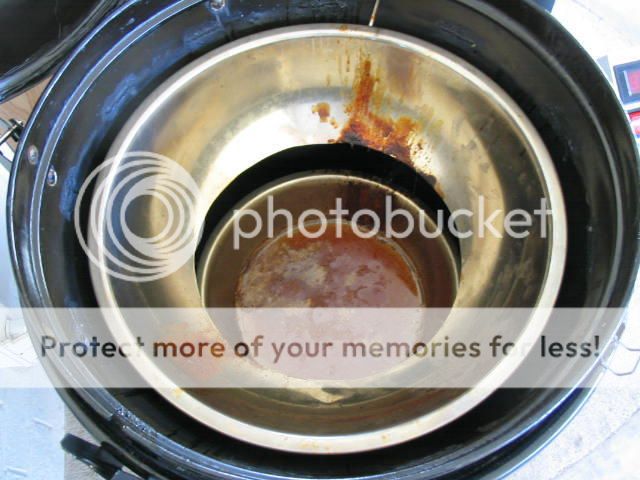
The top drip pan directed the drips to the water pan below. With a light coating of ant-stick spray the cleanup only took a couple minutes.
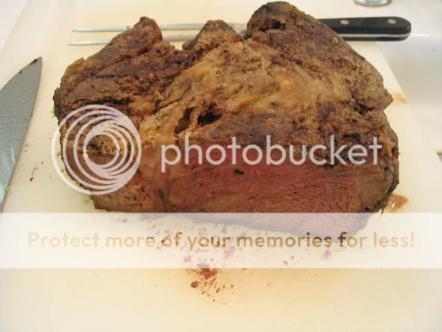
Here is a beef chuck roast. Surprisingly moist, sorta tender, and nicely flavored with a one handful of Mesquite chips. The control box meat thermometer was used on this smoke, you can see where the probe was inserted in the middle. It hit medium rare on the first try.
Additional posts below cover the construction details........
Here are details of my high tech DIY UDS. It might give you ideas on how to build your own so feel free to copy anything that might work for you. Construction details follow in the posts below. These are not step-by-step, just a review of what I remember over the six months or so during construction.. This is a work in progress so there are a few modifications that will be made as time goes by and I'll update accordingly.
Background
Just for fun, I've bought, then sold, a number of used smokers off Craigslist over the years, both electric and charcoal, to find out what works best for me. My latest is a Masterbuilt 30" electric. It works OK but it has some drawbacks. After a while, I started thinking about a DIY drum smoker.
Although I prefer the taste and texture resulting from charcoal smoking, I'm getting lazy in my old age and wanted instant start up, minimum hassle, and minimum cleanup. Low operating cost was also a factor. And one big constraint was size: not much free space in the covered patio area. All these factors led to an electric smoker/roaster with a compact, vertical design.
Here is a partial list of the features I wanted:
1) A rotisserie for self-basting. I noticed that a spice rub is much tastier when it is frequently basted but I'm too lazy to do it by hand. 2) Precision temp control. I like the idea of tightly controlling the smoker temp as the final meat temp is approaching. 3) Low operating cost. With a typical electric a four hour smoke turns out to cost less than a buck in electricity. Much less if the smoker is well insulated - the goal was 10 cents per hour. 4) Easy cleanup. Although internal soot build up is not an issue for me, I don't like the accumulation of food splatters in my smoker. 5) Big cooking surface area. I often do a big batch with extra for the freezer. And 6) Lots of flexibility: with water pan, without; with lava rock, without; with hot smoke or cold smoke; high temps for roasting and browning, and low temps food dehydrating like jerky.
In short, I wanted it all. So I finally settled on a DIY drum smoker. Here is the result:
Wide Mouth
Overview
If you look closely at the top photo, the 55 gal drum has been split in two, separated by a rubber gasket. This forms two insulated housings for the internal parts. Below is a photo of the smoker in two pieces. They are held together by locating pins to keep the two aligned. Latches are planned later. If you are into electric smokers the photo below might remind you of an electric Brinkmann unit -- you guessed it.
Actually the drum itself is not a key part of the smoker. It simply forms the outside shell for the parts inside. At the seam between the two, the top and bottom are sealed off with a welded round sheet metal ring, then with gaskets.
Layout
There are three main assemblies inside:
First the top half consists of a UniFlame 360 sq in Kettle Charcoal Grill from Walmart which forms the hinged top, top grill support, and rotisserie shaft cutout. Second, the inside parts are from a Brinkmann (810-5290-4 Smoke'N Grill) electric smoker, less the top, handles, and feet. They look like this:
This top assembly then fit into the Brinkmann lava rock pan containing the heating element and below that the base pan. Then, below that is a custom fabricated auxiliary heating element assembly.
Inside it looks like this:
The third part is the bottom sheet metal assembly which contains a Little Chief 250W auxiliary heating element. This second heating element adds heat to the main heating element to achieve higher temps, up to 350 deg. Also, the second heating element allows an independent and controllable source for burning the wood chips. The drum encloses all these pieces with an insulated space between. When both halves of the drum are together, access to the second burner is through through a door in the side of the drum. By splitting in two there is full access for cleaning plus easy access to the heating elements in case they need replacement.
The UniFlame, the Brinkmann, and the drum were all bought used from Craigslist for $15 each. The custom smoke chamber parts were made for about $50 from a local AC sheet metal shop, and the Little Chief heating element was $20 from eBay. So with less than $100 initially invested I was able to get started.
Highlights
Insulation And Seals
The drum is not really required for this smoker to work. However, it formed an outside housing with about a 3" space between the internal parts. This was filled with fiberglass insulation and fully sealed with silicone sealant.
Since the drum surface temperature does not exceed 150 deg at any one spot, most of the the outside surface is just warm to the touch so the drum's inside wall coating did not need to be burned out. With less heat loss it uses less electricity, higher temps can be achieved, and it makes for easier temperature control. A couple small holes in the top and the bottom provides humidity and pressure equalization.
All the seams have been sealed with 500 deg F high temp silicone to prevent air leakage and to prevent the fiberglass insulation from infiltrating into the cooking space. And the area where the two halves of the drums meet was doubled sealed, first with white fiberglass insulation rope on the inside, then a black rubber gasket on the outside, with the gray fiberglass insulation in between.
High temperature silicone sealant was used to provide a gasket between the top and the rim. In operation, the only leaks are at the rotisserie rod holes. Of course the top vent operates normally.
Rotisserie
The rotisserie was mounted close to the drum body on a bracket to reduce the overall width. But during testing the rotisserie motor got a little hot. Some motors don't seem to last very long, probably due to the heat. To reduce motor temps a polished heat shield was added, plus a small fan was mounted to the back of the motor near the gearbox. With the smoker's internal temps going full blast the motor now runs only warm to the touch.
Cooking Area
The original top UniFlame grill fits as usual. Below that three tabs were installed so a second grill to fit just below.
Below the BBQ grill, two Brinkmann smoker grills fit as usual. This allows for a large cook area.
Double Drip Pans
The original Brinkmann water-drip pan still fits but additional pan supports were added for a deeper stainless pan for longer periods between adding water.
Another drip pan can be added to cover a larger area closer to the top and direct the drips to the water pan below.
This prevents drips from accumulating at the bottom of the smoker. The pans simply lift out for easy cleaning.
Dual Heating Elements
There are two heating elements, the usual Brinkmann element (see previous photo) plus a Little Chief second auxiliary for extra heat and for the wood chips. The aux heating element assembly is mated to the bottom of the Brinkmann base pan.
Here is the rationale: First I wanted as much heat as possible to get the internal temps into the 350 deg range so the extra 250 watts adds to the Brinkmann's 1500 watts. Second, I wanted independent control of heating the wood chips so a pan containing the chips fits directly on top of the axillary heating element.
Ordinarily if the smoker is well insulated and the temperature control is tight, the heating element might not cycle hot enough to keep the chips smoldering. On the other hand, if the heating element is cycled hot enough to get the chips going, then the inside temp might swing too high -- not an easy compromise. And with most electrics, getting the smoke chips smoking and replenished over the course of cooking is sometimes a hassle. With a separate chamber for the wood chips accessible from a door on the side, managing the smoke is a snap. There are internal stops to precisely position the chip pan directly on the center of the heating element.
Control Box
The over-the-top control box was designed to provide as much flexibility in controlling temperature and smoke as possible - initially just for fun and dinking around. Thereafter, much of the features included will likely not be used much.
The top display is a calibrated meat thermometer. This is extremely important to minimize opening the top to check the meat temp. When not in use the probe is stored away in the control box mounting.
The square display next to the power button is a dual mode industrial PID temperature controller. (See: wikipedia.org/wiki/PID_controller ) This reads the thermocouple inside the unit and cycles the heating elements on and off to keep the desired temperature.
The two LEDs under the power switch indicate the on-off status of the main and aux heating element.
There are three toggle switches; from left to right: The main heating element can be manually be set to "on" or "off" or connected to the controller in "control." Same for the center switch for the aux heating element. The third switch links the aux heating element to the controller normally, or in reverse.
The two knobs control the power delivered to the heating elements through a solid state AC controller in both the "on" and "off" state. The left knob will add heat when the controller turns the heater off, from zero in the leftmost position and about 700 watts in the rightmost position. The knob on the right controls the wattage when the heating elements are on, from about 700 watts in the leftmost position to about 1750 watts in the rightmost position. Different settings are used depending on the configuration of the temp controller.
Results
With the very first automatic PID setting, the temperature controller easily held plus-minus one degree, about as good at it gets. After the top is lifted the unit gets back up to temp quickly - better than expected, even without the lava rock. But it takes quite a while for the smoker to get from 250 deg to 350 deg so extra time had to be figured in. It takes about an hour for the water pan to get to a gentle boil. With an outside temp of about 100 deg, the unit pulled an average of about 600 watts when set at 250 deg. So a four hour smoke runs less than $0.40 in electricity at our $0.15 KWH rate.
Here are a couple chickens. For testing these were placed with the legs in the middle so most of the drips would fall toward the outside. Only two handfuls of cherry wood chips were used for taste on the mild side.
The top drip pan directed the drips to the water pan below. With a light coating of ant-stick spray the cleanup only took a couple minutes.
Here is a beef chuck roast. Surprisingly moist, sorta tender, and nicely flavored with a one handful of Mesquite chips. The control box meat thermometer was used on this smoke, you can see where the probe was inserted in the middle. It hit medium rare on the first try.
Additional posts below cover the construction details........
Last edited: